- New


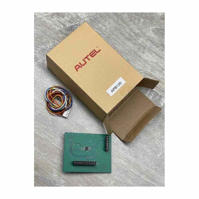
Autel APB130 Add Key VW MQB NEC35XX Adapter For XP400 PRO
Work with Autel XP400 PRO Key Programmer Tool Device
Supported Vehicles:
VW:
Arteon 2017-2019
Golf 2013-2019
Passat 2015-2019
Polo 2015-2019
T-Roc 2018-2019
Audi:
A1 2019-2019
A3 2021-2019
Q2 2017-2019
Q3 2019-2019
Seat:
Arona 2018-2019
Ateca 2018-2019
Lbiza 2018-2019
Leon 2013-2019
Tarraco 2019-2019
Toledo 2013-2019
Skoda:
Octavia 2013-2019
Fabia 2015-2019
Superb 2015-2019
Kodiaq 2017-2019
Kamiq 2020-2019
Radid 2013-2019
Chip Types :
D703532 - D70F3525 - D70F3526 - D70F3537 - D70F3529
Note: You Need To Have Autel XP400PRO And APB130 Adapter To Use This Function
-D70F3525-
Step 1: Prepare the APB130 adapter.
Step 2: Connect the programmer to the 12 V DC power adapter.
Step 3: Carefully check the current component circuit board and find the corresponding circuit board in the following figure.
Step 4: Find position T1 in the figure and perform pin lifting (After the pin is lifted, the FVDD line needs to be connected to the lifted pin), or find position T2 in the figure where line cutting is needed and perform line cutting.
Step 5: Connect the programmer and the APB130 adapter as shown in the figure and read the data.
-D70F3526-
Step 1: Prepare the APB130 adapter.
Step 2: Connect the programmer to the 12 V DC power adapter.
Step 3: Carefully check the current component circuit board and find the corresponding circuit board in the following figure.
Step 4: Find position T1 in the figure and perform pin lifting (After the pin is lifted, the FVDD line needs to be connected to the lifted pin), or find position T2 in the figure where line cutting is needed and perform line cutting.
Step 5: Connect the programmer and the APB130 adapter as shown in the figure and read the data.
-D70F3529-
Step 1: Prepare the APB130 adapter.
Step 2: Connect the programmer to the 12 V DC power adapter.
Step 3: Carefully check the current component circuit board and find the corresponding circuit board in the following figure.
Step 4: Find position T1 in the figure and perform pin lifting (After the pin is lifted, the FVDD line needs to be connected to the lifted pin), or find position T2 in the figure where line cutting is needed and perform line cutting.
Step 5: Connect the programmer and the APB130 adapter as shown in the figure and read the data.
-D70F3532-
Step 1: Prepare the APB130 adapter.
Step 2: Connect the programmer to the 12 V DC power adapter. Step 3: Carefully check the current component circuit board and find the corresponding circuit board in the following figure.
Step 4: Find position T3 in the figure and perform short- circuiting.
Step 5: Connect the programmer and the APB130 adapter as shown in the figure and read the data.
-D70F3537-
Step 1: Prepare the APB130 adapter.
Step 2: Connect the programmer to the 12 V DC power adapter.
Step 3: Carefully check the current component circuit board and find the corresponding circuit board in the following figure.
Step 4: Find position T2 in the figure where line cutting is needed and perform line cutting.
Step 5: Connect the programmer and the APB130 adapter as shown in the figure and read the data.
No customer reviews for the moment.